 |
|
|
|
 |
 |
| by Rick J.
Kelley |
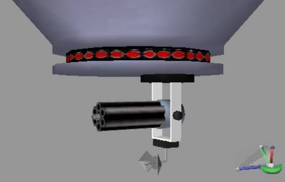
| In this tutorial, we will create a fairly
simple model using some of the basic creation
tools in GameSpace. The image below shows what we
will attempt to build, and if all goes well, you
will have a suitable model to put into a game
engine. |
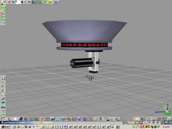
Finished project of CeMac
The story behind this model and
its purpose goes like this: “Hello Jim, this
is your mission if you decide to accept is, build
a Ceiling Mounted Automatic Cannon, or better
known by its buzz word, CeMac!”
As the smoke from the
self-destructing mission briefings DVD burns your
nostrils, you quickly sketch out the design on
some toilet paper so it you can flush it, or
swallow it, in case you get caught with the
design.
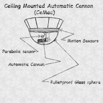
Figure 1.0.1 Sketch of model to build
|
| Getting ready to
use the GameSpace editor |
| When you start up the GameSpace editor, you
might want to configure it for your modeling
preferences. In this tutorial to start out with,
you might want to use the 4 View configuration.
This will give you a view from the top,
perspective, front, and left. This is a fairly
standard way of working with your model in a lot
of editors. To set up for 4 Views, click on the
Configuration Library Icon as shown in Figure
1.0.2. 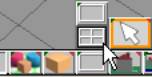
Figure 1.0.2 Views Icons and 4
View choice
|
| Using the
Primitives to start your model |
| This model was started with using a Cylinder
primitive. All primitives in GameSpace have
options as to how to create them. You will access
these options in two different ways. The first
method is done by right clicking on a primitive
and then typing in a number in on of the text
boxes provided for its options. Take a look at
Figure 1.0.3 to see where the primitives are
located, and the dialog box containing the
options when one of the primitive icons is right
clicked.
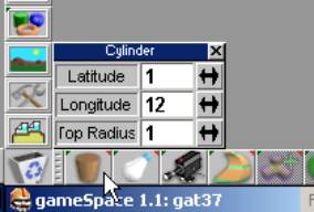
Figure 1.0.3 Cylinder Primitive
options with right clicking
|
We will be
using this method to set the cylinder primitive.
Type in 1 for the Latitude text box option. Type
in 12 for the Longitude text box option. If there
is any number besides 1 in the Top Radius text
box option, type in 1. After you have set your
options correctly, you will now activate the
Cylinder Primitive Icon so you can use it. Move
your cursor into the Top viewport and try to left
click in the center of the grid. You may be
wondering what the red and green bars are for
when you create the primitive. If you click
somewhere off of this primitive, they will
disappear and you may accidentally create another
cylinder primitive as you are still in Cylinder
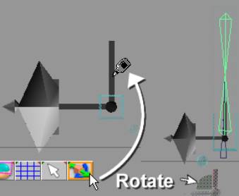
Primitive creation mode. Take a look at Figure
1.0.4 to see an illustration of these bars and
what they are, and a taper effect it could create
if you click and drag the green bar.
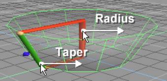
Figure 1.0.4 Taper and Scale effects of
clicking and dragging bars
|
| Try to imitate the shape as in Figure 1.0.4,
as this will be the base of our CeMac device.
(The Magic Ring has some many features that we
haven’t explored in this tutorial and I
suggest you read up on it in the user’s
manual). Now you need to click on the Object
Tool to deactivate the primitive creation tool.
If you don’t deactivate it, you will keep
creating cylinder primitives! (In case you do not
know where this tool is, see Figure 1.0.5).
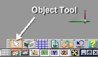
Figure 1.0.5 Object Tool
location
To continue onto make the base of
our CeMac, we will be using features of GameSpace
to make it a bit easier. You can hide an object
from view in what is called the Scene Editor, or
sometimes referred to as SE. Click on the Scene
Editor Icon as shown in Figure 1.0.6.
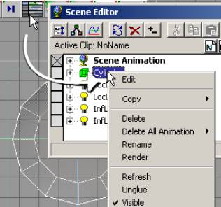
Figure 1.0.6 Scene Editor and
how to hide an object
If you click on the Visible
setting, it will hide the object from view that
was highlighted by its selection in the scene.
There is one problem though; you could still
accidentally select it, even though it is hidden!
To avoid this with overlapping objects, its best
to use a handy feature of GameSpace, called
Layers. Layers can contain objects that you can
hide and lock, to keep from selecting and seeing
objects that are in a layer. Layers can even have
a color so you can see the objects in these
layers with a wireframe of this color you haven
chosen. You do this by right clicking on a layer
icon and use the color wheel to change its color
and the wireframe color the objects. Lets create
a new layer, and put this cylinder in it now to
avoid what we just discussed for the future
creation of our model. Click on the Add New Layer
Icon as shown in figure 1.0.7.
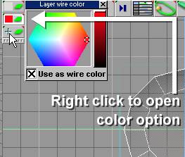
Figure
1.0.7 Add New Layer Icon and color options
Now we will change the options on the Scene
Editor to make it easier to move objects to
different layers. It is pretty simple in the
Scene Editor to change an objects layer. You
click and drag an object to the layer of your
choice and drop it on the layers as Figure 1.0.8
shows how to do this.
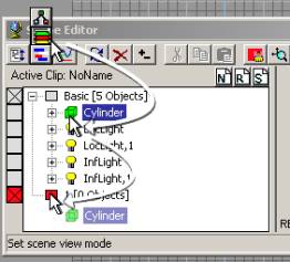
Figure 1.0.8 Changing objects
layer order in the SE
Now you can lock off the
layer and hide it as well. The best part of this
way of doing things is, that you can hide, and/or
keep from selecting multiple objects and have
objects that are related to each other into a
layer for ease of use. Let your imagination run
wild!
Take a look at Figure 1.0.0
for a demonstration of how to Lock, Hide, or Show
a layer.
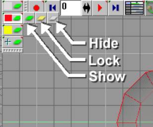
Figure 1.0.9
Changing Layer properties
You will now
Lock this new layer by clicking on the Lock icon
from the flyout menu if you haven’t already
done so.
| Note: If
you have hidden the object by using
the method of right clicking on the
object and unchecking Visible, you
may get confused when you also have
hidden the layer. If you do this and
try to make the object visible, it
will seem to not work and get you
frustrated, as the layer was hidden
and will not allow objects in the
layer to show until you click the
Show Layer in the Layer properties. |
Try
selecting the cylinder. You will find that its
impossible to select this object as it is on a
locked layer. For now unlock the layer so we can
still work with it.
Before
we go on, a word of advice is warranted here;
save your work before you do any major changes to
your work. I always save in steps, and saving
them to a directory by the models name. So for
example if I were to make a Boolean operation and
the file name was “gat10.scn,”
I would do a Save As before attempting it and
name it “gat11.scn.”
|
| Setting up some
extra lights for your scene |
| You may notice that the bottom of the
cylinder is dark, so lets add one light to the
front that is halfway between the cylinder and
the one light that is already in front. This
light will be what is called a Local Light. Click
on the light creation set of icons, move up the
fly out menu to find Local Light and click to
place it behind the shape on the North side of a
compass. Set this lights Intensity property to
0.7. Now make a copy of this while holding down
the Ctrl and C keys with you mouse pointer
hovering over the top of the light you created.
Let go of the keys and drag this to the North on
a compass point. While in Object mode, select the
two lights you have created, and while holding
down the Ctrl key, you can make a window
selection and then move them down past the floor
of the scene. Using this selection of more than
one object at a time and moving, scaling, or
rotating them is a very useful feature! I use
this often after learning this tip. (Refer to
Figure 1.2.0 to see the details of what has been
discussed).
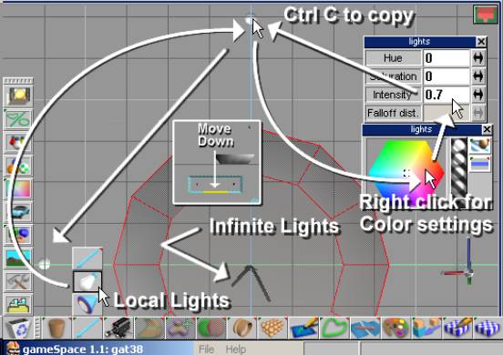
Figure 1.2.0 Light Icons, placement and
settings
We need to do one last thing
before we are ready to shape this cylinder
primitive. The material of this cylinder may be
still to dark to be a cold metal look. You will
change the material by clicking on the Material
Editor Icon, (ME), then open its properties. You
could apply the texture to this cylinder at this
point. You can do this by opening the image
browser, then dragging and dropping the image
into the ME. To apply this new setting or
material, you will drag it to the cylinder as
shown in Figure 1.2.1.
| Note: Once you set or change the
material to something different, every
time you create a new object, it will
assume this new setting. |
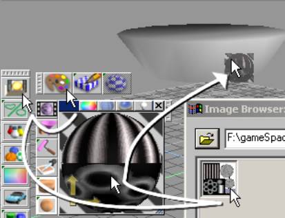
Figure 1.2.1 Material property
settings
Once you have dragged and dropped the new
material, you will see the image applied to the
shape. It is incorrect, and we will fix it later.
For now just turn off the view of the texture by
right clicking on the Draw Icons, and clicking on
the Toggle Use of Textures in Solid Render Icon
in the options, like Figure 1.2.2 shows. This
only works for the active viewport, so you will
have to do it for each one that you wish not to
see a texture on an object.
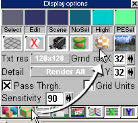
Figure 1.2.2 Display options
property settings
|
| Modeling with the
Sweep, Scale, Move, and Face Delete Tools
|
| Now on to the actual modeling that you have
been so patiently waiting for! Before we will
work on this, move the shape up above the floor
of the scene, as we will be working on the bottom
of this object. The object must be selected. You
may have noticed a blue selector cage around the
active the object, and wondered what its use is.
You can use this to scale, or rotate the object,
as you desire. I will not go into detail of its
use, but you can read more on it in Chapter 1
Introductory Tutorials under the subheading
“1.2 The Selector Cage,” page 3. Simply
click and drag the object up.
We will be exploring the use of the Sweep
tool, or in some modeling applications known as
extruding. This is a powerful tool, as it can add
sections to your model, so you can shape more
complex models. Model makers often use this type
of tool.
The icon to access this tool is currently
grayed out because you are not in an
object’s editing mode. To do this, first
select the object that wish to edit, and then
right click on it. You are now in the Context
Editor mode and should see a wireframe and a see
through look to the object now. There will also
be a new set of Icons to use for editing the
features of any object. These include Face, Edge,
and Vertex modes of editing an object. There are
4 ways to select a portion of the object:
Freehand, Lasso, Rectangle, (window selecting),
and Named Selection. If you do not select any,
you will be in a Context Edit mode, which is very
handy as you can move your cursor over any of the
above mentioned portions of what makes up a
object.
The next step will allow you to see all
available icons for your use, instead of having
to click and hold and then navigate up, or down
the icons flyouts. On the edge of any toolbar,
you should see a dotted looking vertical bar.
Click only once on this. (If you do it twice, it
may collapse the entire bar as one dot, which is
hard to find sometime. You would need to click on
this dot to bring the toolbar back to show its
icons if this happens to you). Now you can select
the faces of the object without fear of selecting
anything on the bottom or sides that do not face
your cameras view of the viewport. Click on the
top of the cylinder to select the polygon at the
top of the cylinder. In the context editor, you
will see the Sweep tool. Click on it now, as it
has a default sweep setting. (You can right click
on it to type in values if you wish). See figure
1.3.0 to see how to do this.
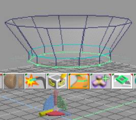
Figure 1.3.0 Entering Context Editing mode
We now have to control the sweep, or extruded
face we have selected. Use the Selection cage to
move it upwards, until it is pretty close to the
original. Click the Sweep Tool once again. Now
you’re going to use the Selection cage to
scale this inwardly, and then move it up to be
level with the last sweep to make the start of an
indentation for our motion detection area of our CeMac. Figure 1.3.1 shows the details of these
sweeps, moves, and scales using the Selection
Cage.
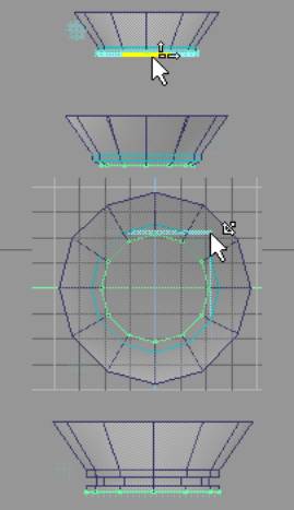
Figure 1.3.1 Using the Sweep
Tool and Selection cage to shape object
Before we continue, pull up a chair and get a
cup of coffee as I am going to give you some
pointers on Low Polygon Modeling, or as some call
it by the buzzword LPM. When you are working with
a game engine, you need to be concerned on how
many triangles are in a model. (Triangles are
sometimes considered as polygons in modeling but
polygons can have more than 3 sides or edges to
them, so be careful when your doing a polygon
count. Your export of your model will probably
use a triangulate on the polygons that may
contain more than two triangles. Quads as they
are known in the modeling community consist of
two triangles to from a rectangle shape.
GameSpace uses a technique while modeling to use
more than one triangle to make complex shapes
easier to work with). The game engine has to keep
track of all of the polygons in use, no matter if
they are displayed or not. It uses a routine to
do what is called backface removal before trying
to draw these polygons on your screen. This can
take up a lot of unnecessary CPU time, so you
should rid the model of polygons that will never
be seen ingame.
Done with the lecture now, so while you still
have that top polygon selected, switch to the
Delete face, then click in the top viewport on
the selected face you have been working with up
to this point. (See Figure 1.3.2). A player will
never see the top portion, as this is a Ceiling
Mounted automatic cannon! Click on the object
tool to deselect to get out of Context Editing
mode.
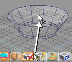
Figure 1.3.2 Face Delete Tool
usage
|
| Using Boolean
Subtraction for complex shapes |
| A word of caution is in order here when using
the Boolean tools. They are very useful when
modeling some complex shape, and they can become
like a drug, as they are addictive when you start
using them. Sometimes when you use these tools,
unexpected things can happen to your model. For
some reason, you cannot foresee what kind of
mathematical calculations that will take place on
your model when you use these tools. Your model
could have extra faces that seem to connect to
odd places on your model when you use it. I have
even seen a whole model seem to collapse in a
mess that looked like a Start Trek transporter
accident after using a Boolean operation on it!
So a word of advice is warranted here; save your
work before you do a Boolean operation, as it may
save your bacon some day! Trust me on this one! If
the base portion of the CeMac is not still
selected and you don’t see the selector cage
around it, click once on the base. If the X and Z
Navigation Toggles are not turned off, turn them
off now, as we want to move only in the Y
direction. Click and drag away from the selector
cage to move the base up off the floor of the
scene. You can refer to Figure 1.4.0 to see
approximately how high, but first we will create
a cube to use for our Boolean operation.
Switch to a screen mode by
clicking on the Display Options Icon and then
move your cursor up to the Draw objects as
transparent outline icon. (Refer to Figure 1.2.2
for a refresher on this).
Create a cube that is only 1
x 1 segment. Refer back to how to set up a
primitive at the beginning of this article if you
need to see how this is done. (See Figure 1.0.3
for a refresher). Click on the Object Tool to
deactivate the Magic Ring mode of the primitive.
If you accidentally deselect the object, (you do
not see the Selector Cage), click on the cube
once to activate the objects Selector Cage. We
are going to squash this cube by its X, and
expand it by its Y axis. Move your mouse cursor
to the front view and close to one of top left
edges of the cube until you see it change to a
cursor with an up and right arrow. (You may see
the cursor change into other shapes, but move it
until you see it take on the aforementioned
shape). You should now be ready to squash it on
its X axis. Move this edge until it approximately
what it appears in Figure 1.4.0. Now do the same
for the top edge, and expand it until you have it
just a wee bit into the base that you created
earlier. Move your cursor over, but don’t
click the cube you created, and press Ctrl c to
make a copy of this cube. We want to be able to
scale this copy by keeping it centered to the
first copy to for accuracy. Now you will need to
set up this cube to use as a subtraction for the
Boolean operation. Scale it on its X axis, then
scale on its Z axis as well to make it larger in
depth. Move it down by its Y axis as shown in
Figure 1.4.0. You are now ready to perform the
Boolean Subtraction.
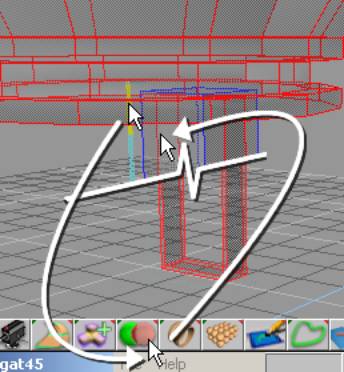
Figure 1.4.0
Copy, Scale, and Boolean subtraction
I hope you’re ready for the magic of
Boolean operations! 1st click on the
object you wish to keep. Next navigate to the
Boolean Subtract tool. Finally, click on the
object you wish to use as a subtraction from the
first item. You can follow these steps as in the
illustration of Figure 1.4.0.
Are you ready for a tool that is not found in
other modeling utilities that is very useful? I
was pretty excited about it when I found it.
It’s called the Polygon Copy tool in the
Context Editor. Another useful tool is the
Polygon Draw, but I will leave you to look up how
to use this in another tutorial or the manual
that comes with GameSpace. We will only use the
Polygon Copy tool.
|
| How to use the
Polygon Copy Tool |
| We need a pivot point for our
CeMac so it can swing up or down when tracking
the enemy. The Polygon Copy Tool comes in handy
for making this in a cylinder shape. Since we
would like to keep it low polygon, we will keep
the cylinders Longitude to 8 sides. You will need
to enter the Context Editing mode on the Boolean
Subtracted cube, so right click on it now.
Navigate to the Polygon Copy Tool and right click
on it to set its properties to 8 for the number
of sides for the polygon to create. Move your
cursor near the bottom of what we will now refer
to as the bracket of the CeMac on the outside
edge in the right viewport. Take a look at Figure
1.5.0 for details on how to do this.
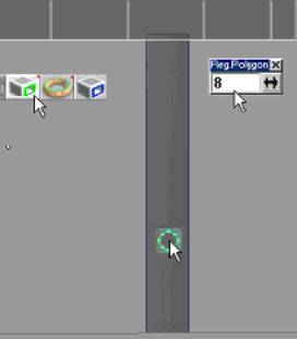
Figure 1.5.0 Polygon Copy Tool usage
You may need to
scale this polygon up in size, so click on the
Point Scale Tool to do this and click and drag
with both mouse buttons. If you need to move this
polygon to look more centered, click on the Point
Move tool and move it around until it looks best.
Refer to Figure 1.5.1 for what these tools look
like in the Context Editor.

Figure
1.5.1 Point Scale, and Move Tool Icons
Usage of
the Sweep Tool is the next order of business.
Click on the Sweep Tool to sweep this polygon
outward and move it to look like a pivot point
for the AC.
| Note: You might have some trouble
with trying to sweep right after using
the Polygon Copy tool a few times. If
this happens, click on the object tool to
deactivate the Context Editor. Right
click to activate the Context Editor.
Then right click on the Sweep tools to
enter the number in the Z Segment
properties. |
Now you will
need to do this to the other side of the bracket
for the CeMac. Just follow the same steps, but
when you are ready to scale and move the polygon,
try to line it up with the opposite sides, while
you’re in Draw objects as transparent
outline icon. If you forget how to do this, refer
to Figure 1.2.2 and the text above it as a
refresher on this. After your second sweep
operation, you should have what Figure 1.5.2
shows.
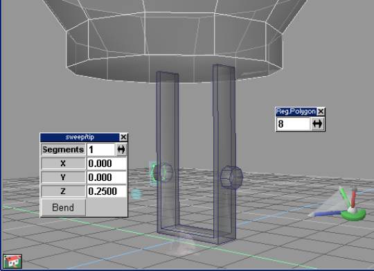
Figure 1.4.4
Finished bracket
The next step
will be to create the AC component of the CeMac.
We will be using the Point Edit: Vertices Tool in
the context editor to achieve the look of this
for low polygon use.
|
| Using Separation
and working at the Vertex level of your model |
Sooner or
later, it will come to editing at the vertex
level, the smallest component of 3D modeling. And
in this section we need to create a cylinder
primitive and scale some its vertices down in
size to create the illusion of a 6-barrel
automatic cannon. But first our bracket looks a
bit to large so let’s review our Point Edit:
Scale option of the context editor. If
you’re still not in the Context Editor mode,
right click on the bracket. Click on the Point
Edit: Faces Icon and the Select using rectangle
Icon. Make sure the Backside option is checked in
the selection options. (Right click on the Select
using rectangle Icon if you have forgotten how to
access this feature). Drag a window around all of
the faces to select all. Click on the Point Edit:
Scale Icon. Make sure all the Navigation Toggles
is turned on. (As a reminder refer to Figure
1.4.1 to see where these are located). Now click
and drag down and to the left to scale it down.
Click on the Point Edit: Move Icon, and lock off
the X and Z Navigation Toggles. Move the bracket
back up into the base of the CeMac. Now create a
Cylinder Primitive that is 1 Latitude, 12
Longitude, and 1 Radius segments in proportion.
Use the primitives Magic Ring to scale this down
to fit inside of the bracket. You will need to
rotate this, and we will be using the object info
dialog to do this. Right click on the Object Tool
to bring up this dialog and type 90 in the X
Rotation axis. Take a look at Figure 1.5.0 to see
how close you come to what the image depicts.
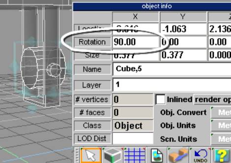
Figure 1.5.0 Using object info
for rotation
You could also use the object
info dialog to move, and to size the object. You
can even use math operators on the Size, Rotation
and Location axis, e.g. if you type /2 in any of
the Size axis, you would scale the object on that
axis down to half its size. You could also use
the Selector Cage to rotate the object, and
combine the Grid snap feature to help to make it
snap in a orthogonal way.
Enter the Context Editing mode by
right clicking on the cylinder primitive. Select
the front face. Click on the Sweep tool. Use the
selection cage to move this sweep outward ly to
look like Figure 1.5.1.You should try to make the
whole of bracket and AC center to the base. Click
on the Object tool to deactivate the context
editor, and hold down the Ctrl key and click on
the bracket and move the bracket and the AC on
the X axis to center it. See Figure 1.5.1 to
follow these steps outlined in this paragraph.
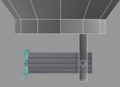
Figure 1.5.1 Sweeping and
centering the AC
To use the Separation tool, you
will need to select only the cylinder or the AC
part of the gun. Click on the object tool until
nothing is selected. Then click on the AC
cylinder, and right click on it to enter Context
Editing mode. Click on the Point Edit: Face Icon
and the Select using rectangle Icon. Select on
the part that you made with the Sweep tool
previously. Click on the Separate selected part
of object Icon. You will see a piece of it
separate and close both portions with a face of
its own. Take a look at Figure 1.5.2 to see how
this was done.
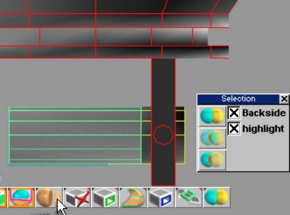
Figure 1.5.2 Separating a
portion of the AC
We will be scaling this down, but
only on two axes. Turn off the Z axis in the
Navigation Toggles, (located at the bottom
right). Move to the front viewport and click and
drag with both the right and left mouse buttons.
Scale it down as shown in Figure 1.5.3
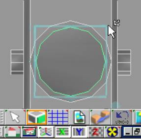
Figure 1.5.3 Scaled down part of AC
The separated cylinder needs to
have twice the amount of edges that it presently
has. We will use the Quad Divide Tool to do this.
Click on this tool now. Right click on it to
enter the context editor. We have what we want,
but we need to get rid of the extra stack that it
created in the middle of the cylinder. This is
pretty easy if you use the tool that you are
already familiar with, the Separate Tool. Click
on the Point Edit: Face Icon and the Select using
rectangle Icon. Do a window select on the back
portion of the cylinder to select all the faces.
Click on the Separate selected part of object
Icon. The editor will deactivate as before and
have the separated portion selected. Delete this
by pressing the delete key on your keyboard.
Click on the remaining portion of the cylinder
and right click on it to enter the context editor
once again. Take a look at Figure 1.5.4 to bring
you up to speed on what we have done so far.
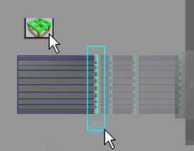
Figure 1.5.4 Quad Divide and Vertices
select and move
|
| Finishing up
details of the AC |
| We are going to finish up the model part of
the Automatic Cannon by using features that we
have already discussed some in different ways. So
get another cup of coffee, as this part may be a
little tricky! Select the faces in the front.
To make sure you only get the front faces, open
the Selection properties by right clicking on a
Select using icon in the Context Editor, and
uncheck Backside. A good tip here would be to use
the Grid Snap mode. Click on the Grid Toggle Icon
to turn this feature on. This will allow you to
be more precise in your creation. Click the Sweep
tool. Move these new faces all the way back to
align them with the faces your sweep started
from, meaning flatten them on the Z axis plane.
Also scale them down in size by using the
Selector Cage, (see Figure 1.6.0).
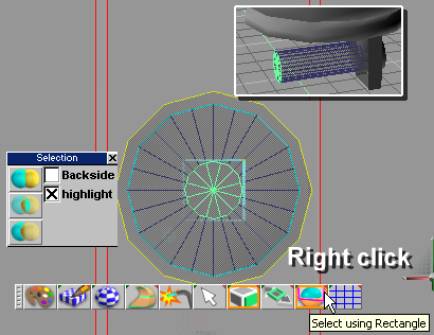
Figure 1.6.0 Selecting, sweeping and
scaling faces
On to editing in Point Edit: Vertices mode. I
know you have been waiting a long time for this!
To make the shape of the Auto Cannon gun look
like it should, you will need to select only a
few of the vertices from the front and back.
Click on the Point Edit: Vertices and the Select
using rectangle Icon. Do a window select on
vertices as illustrated in Figure 1.6.1 and snap
and weld the vertices together. Use the Weld
Vertices Icon to snap and weld them together.
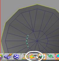
Figure 1.6.1 Corrected vertices
to form a hex shape
Repeat these steps to go around full circle,
welding 3 vertices in the same manner until you
have what Figure 1.6.2 shows. You will have to
adjust these vertices by moving them around to
make the Hexagon shape. Hint: use the scale on
some of them with either the X, or Y turned off
to flatten vertices in a direction. Also turn of
X or Y axis to move them.
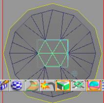
Figure 1.6.2 Corrected vertices
to form a hex shape
Before you start this next step,
I will give you a hint to increase your speed in
making models in GameSpace: use the space bar to
deactivate the Context Editor after you do a
sweep and scale then to right click to enter the
Context Editor once again. This is because it
seems to want to use the settings of your
manipulations and can cause needless tweaking
after you do a second sweep. This will not always
have to be done, but in the creation of metal
looking parts, this is the best method I have
found to work. To create a bolt and rotational
axis for the AC part of the CeMac, you will sweep
this face out, and move it into position so that
it will just protrude just a bit away from the
gun barrels. Use the familiar Selector Cage to
help to do this. Sweep it again, move it back to
meet where you swept it from, and scale down.
Sweep once more. Look at Figure 1.6.3 to see the
final look of how I accomplish this.
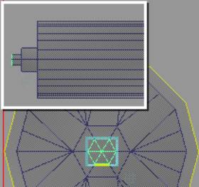
Figure 1.6.3 AC details
Time to turn the Backside option
on again for this next step. Select the vertices
as shown in Figure 1.6.4 and scale them down to
form a sort of flower shape.
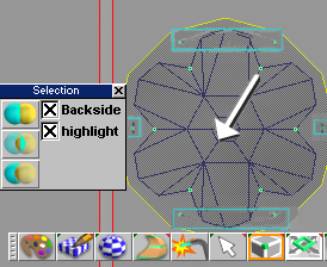
Figure 1.6.4 Forming the
barrels for the CeMac
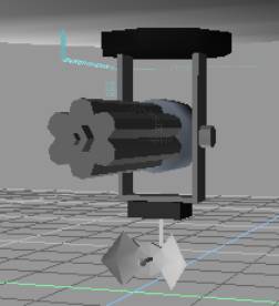
It’s starting to look a
lot like what we envisioned now! One last thing
we should do before starting another section is
to apply a more of a flat shaded look to the
cannon. Click on the Material editor as Figure
1.2.1 illustrated. There are two Icons near the
lower right of the Material Editor that has to do
with how the materials shading will be applied.
We are looking for the Faceted setting in the 2nd
from the bottom icon, and the Sphere on the
bottom right icon. Drag the color slider to a
gray value of about 148 on all the rgb colors.
Drag this new material to the AC. Figure 1.6.5
shows the desired results.
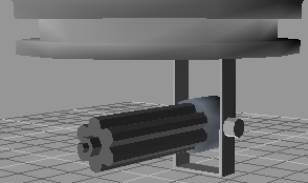
Figure 1.6.5 Material change to
Faceted on AC
|
| Creating a
Parabolic antenna tracker for the CeMac |
| No sentry gun would be complete without a
parabolic antenna. The first step will to be to
make the gearbox for this device. This will be at
the bottom of the bracket created for the CeMac.
Create a cube with only 1 segment dimensions.
Scale this down using the Magic Ring and then the
Selector cage to squash it a bit. Apply a black
material to it like in Figure 1.7.0. 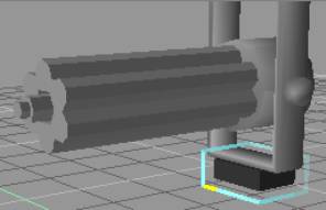
Figure
1.7.0 Gearbox add to bracket
Create another cube and scale it down in size
to make a small block to be used as a pivot bar.
Enter Context editing mode and select the top
vertices and move them up to meet the inside of
the gearbox just created. Apply a white flat
shaded material for this bar. You will need to
move and rotate this bar to make it fit the
gearbox, but you have all the necessary
information now to do this on your own.
We need to create an axial device for an arm
to swivel on. Create a cylinder with the number 8
in the Longitude setting for the cylinders
property options. Create this cylinder and resize
rotate it to fit the end of the pivot bar, and
then apply a black material with a smooth shading
as shown in Figure 1.7.1
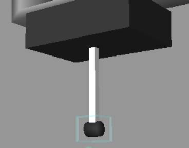
Figure
1.7.1 Pivot bar and axial device for the
parabolic antenna
You can copy the pivot bar to make the
extension bar that will connect the parabolic
mirror to the axial device. Rotate this bar to a
right angle to the pivot bar, and move the
vertices in the context editor as before to shape
this bar so the back edge will set inside of the
axial device as the pivot bar does now. Before
moving on to the creation of the parabolic
antenna, lets take a close look at what it should
look like in Figure 1.7.2.
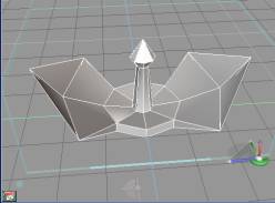
Figure
1.7.2 Parabolic antenna close up
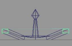
You may notice that it has a somewhat bow tie
look to it. The original shape started out life
as a Cylinder Primitive. Using the Selection cage
helped to create this shape.
Start off with a Cylinder Primitive set to 1
Latitude, 1 Top Radius, and 8 Longitude segments.
Use the Magic Ring to scale it down to size.
Click on the Object Tool to get out the Magic
Ring mode. Right click on this to enter the
Context Editor. Click on the top face and click
on the Sweep Tool. Move your cursor as shown in
Figure 1.7.3, and scale inwardly.
Figure
1.7.3 Sweeping and scaling added section
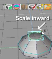
Now use
the selection cage to move this slightly inward
by grabbing the middle portion of the selection
cage. Press the Space bar to exit the Context
Editor, and then right click to enter it again,
as this will eliminate erroneous sweeping in the
next step. Sweep this section again. Scale it
inwardly to give it a taper look. Sweep again and
scale outwardly to form a diamond shape. Finally,
use the Tip Tool to create a point and then move
it down in the front viewport as shown in Figure
1.7.4
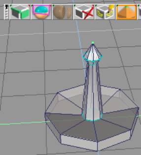
Figure
1.7.4 More Sweeps and a Tip operation
Now you will select the side faces and sweep
them. Use the selection cage scale feature to
make it larger as shown in Figure 1.7.5.
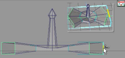
Figure
1.7.5 Sweep and scale of the outer faces
I should pause here to refresh you on how to
hide objects to make it easier to work on parts
of the model. Create a new layer. Select the
start of the parabolic antenna shape you have
made. Open up the Scene Editor. Drag this bowl
shape to the newly created layer. Hide the base
layer. Now all the other parts shouldn’t
distract you! I also recommend that you either
create a layer for the lights or have all the
parts in another layer besides the base layer.
This is because if you hide the layer containing
the lights, all the model parts will go dark!
Refer to Figure 1.0.7 and Figure 1.0.8 for a
reminder on how to do this.
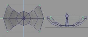
You will shape this figure by scaling the ends
down a bit. If you remember to exit and enter the
Context Editor by pressing the Spacebar, and the
right clicking, you can again save yourself some
unneeded editing. Hint: you may have to use
the Context Editors Scale and Move features if
things seem to not work as planned. Use this in
combination with the Navigation Toggles to help.
Pull the edges up to start to form the
parabolic look to the Antenna. Sweep the edges
again. Again scale and move the edges. For the
final look snap and weld the vertices as shown in
Figure 1.7.6
Figure
1.7.6 Start of the parabolic shape
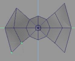
Sweep once more and move this section up and
scale it a bit. Take a look at Figure 1.7.7 to
see what it should look like at this point.
Figure
1.7.7 Further shaping
Now snap and weld the ends as Figure 1.7.8
illustrates showing one end and others ready to
be welded.
Figure
1.7.8 Welding of edges
Finally, weld the tips together. Exit the
Context Editor, and use the Selector Cage to
scale this to fit the look of your other pieces.
Add one small cylinder so it will look like the
bracket you made will be using it to rotate with.
(I added a black smooth shaded material to it, to
make it stand out more). You should have it
looking similar to Figure 1.7.9
Figure
1.7.9 Look at finished CeMac
That’s it! Your finished with the
creation of the parabolic antenna for your CeMac!
It should look similar to the Figure 1.7.2 that
we looked at before we started working on it. Are
you ready to animate it? I hope so as this is
what the next section will cover.
|
| Making a simple
animation for the antenna |
| We would like to see this antenna rotate so
we need to use a skeletal system of a sort, as
many animators now use this form of system to get
a model to animate. Even if its mechanical in
nature, a skeletal system can be a handy way to
work with your model. And best of all, you can
save your animations to be reused for a similar
model! First, if you haven’t already done
so, create a new layer to put the parts of the
antenna into a separate layer on its own. This
would not include the bracket, or the gearbox.
Put only the parabolic antenna, the pivot, axial
device and extension bar that will connect the
parabolic mirror to the axial device,
Hide all layers except for the one that
contains the above items, so they will not
accidentally attach to the joints that we are
about to create. At this point, I have to give
you a gentle reminder. You should save your work
and make a backup of it just in case you make a
mess of something!
To get this to rotate, first select the axial
device. Find the Add shaft joint (1D rotation 1D
translation) icon and click on it. You should see
the glue cursor appear. Click on the pivot bar.
You now should see a joint appear.
Congratulations! You now have a joint you can use
to swivel your parabolic antenna on. You could
test your work so far by clicking and dragging on
the Rotation Control that appeared when you
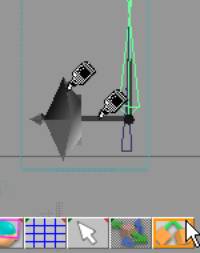
created this joint. Take a look at Figure 1.8.0
to see what we should have by now. Again I have
to say, save your work before experimenting!
Figure
1.8.0 Creation of joint and Rotation Control
The final thing we will do with this is to
glue the other pieces to this joint, so they will
rotate with the pivot bar and the axial device.
Find the Glue Child Icon. When you click on this,
you will see the same icon as before. Take a look
at Figure 1.8.1 to see what this icon looks like.
Figure
1.8.1 Glue Child Icon
Now to
set the animation. Open the Scene Editor and
click on the icon and find the Clip View mode
icon. Click on the Auto Record button. Type in 15
in the Keyframe text box. Use the Rotation
Control to rotate it the antenna at a 45 degree
angle. Type in 30 in the Keyframe text box, and
then rotate the antenna another 45 degrees. Type
in 45 in the Keyframe text box, and rotate it
still another 45 degrees. For the last Keyframe,
type in 60 and rotate another 45 degrees. Now try
your animation by clicking on the VCR like play
button. Woah! You have an animation!
Congratulations! Take a look at Figure 1.8.2 for
details on the Scene Editor and locations of
where these features are.
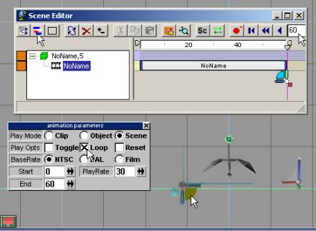
Figure
1.8.2 Animation using the Scene Editor features
Unhide all your parts and run that animation
one more time to see the full thing in action.
One last thing if your going to have a loop of
this, you need to move the Timelines Ending Time
control back one frame, so if your going to loop
this animation, it wont cause a pause that
appears as a jerk in the animation. (See the
manual Chapter 19 under the subheading The Track
Plane for reference on how to use the animation
part of the Scene Editor).
|
| Working
with the UVE |
| One last thing before we leave this tutorial.
Let’s figure out how to start using the UVE
or how to apply a better textured look to our CeMac. Select the base of the Cemac that we
already have textured. Right click on it. Select
the tapered portion that we first started out
with. Click on the UV Mapping Editor Icon. You
will now see the portion on a flat plane ready
for you to resize and move to a place on your
texture that you have created. The UVE is much
like the modeling feature we have used so far,
with Scale, Rotate, and Move feature and the same
selection features as we are already used to. I
have just got you started so get to it! You
should have it looking like I did. When you have
finished with the base, unwrap the AC portion.
Take a look at Figure 1.9.0 to see the UVE in
action, and the finished product in Figure 1.91!
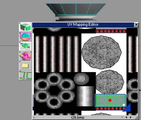
Figure 1.9.0 Using the UVE by
scaling and moving selected piece
Finished product of CeMac
|
| |
|
| |
|
| |
|
|
|
 |