|
The color of your model determines the color of the lines and
vertices in the UV Mapping Editor, so it is worth painting your
object with a solid color, using the plain Color shader, and
choosing the color of your model to make it easier to view (you
could even color different sections of your model differently,
and they will show up with different colors in the UV editor).
The best way to control the size of the image that the UV
Editor saves is to paint your object with a texture map of the
correct size. For example, if you want to use a texture size of
512x512, then create an empty .BMP format image at that size,
save, and paint your object using that file as a texture map.
Note that this will change the background in the UV Editor - it
will match the image file. The colors of the lines will continue
to match the previous colors from the Color shader that was used
previously.
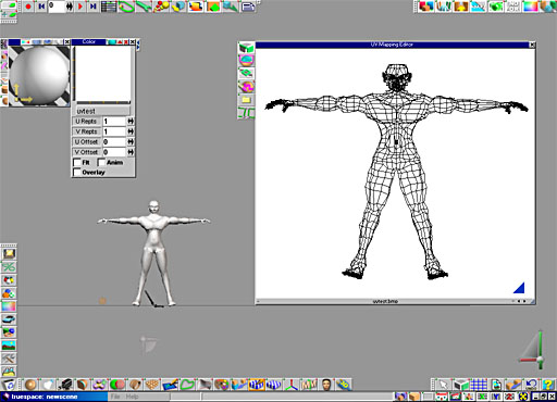
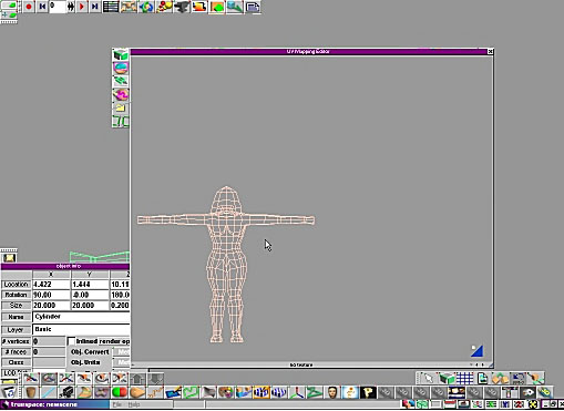
I like to paint my model a solid black color, and then create
an empty image file that is plain white and paint that onto my
model in place of the previous solid black. Opening the UV
Editor then gives me a white background in the UV Editor, with
black lines for the model's geometry, similar to what you can
see below:
One key point to remember as we work - every polygon must be
accounted for! That is our goal, and keeping that in mind can
help.
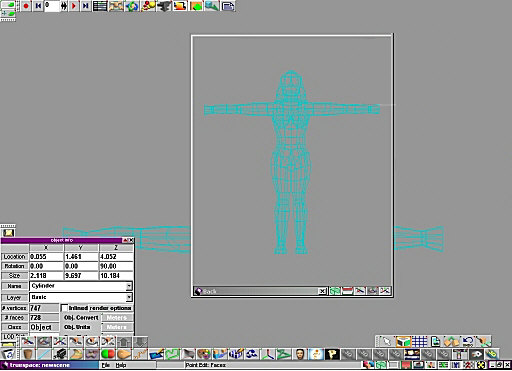
To being creating our UV mapping, first select your model and
open a view from the back of the model. Select the Point
Edit: Faces tool, and then select the Select Using
Rectangle tool which will let us click and drag over our
model to select our faces. Before we do that, though, right
click on the Select Using Rectangle tool and make sure
the Backside is unchecked. With this unchecked, only those faces
which are actually facing us when we use the tool will be
selected. Others that are facing away (on the backside of the
model) will not be selected.
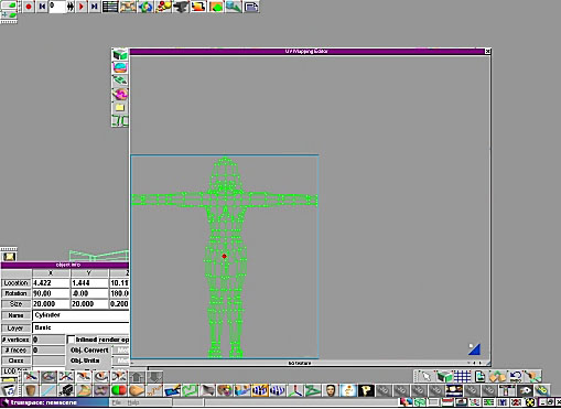
Below is our model in Point Edit mode, waiting for us to
select the faces:
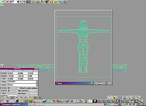
Now click and drag, and this will select all
faces on the back of the model only. Below is what you see once
the faces are selected using the Select Using Rectangle
tool:
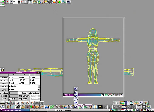
Now select the Planar UV Projection icon
(you can see it in the screen below on the fly-out menu). This
will apply a planar (flat) UV mapping. The important thing to
note about apply UV mapping is that it ONLY applies to the
selected faces. This allows you to assign different UV mapping
to different parts of your object. The affected faces are
highlighted, and in this example, they turn yellow (see below).
Those faces now have their own, unique, flat UV mapping applied
to them.
With the UV mapping still selected, the
Object Info box (right click the Object Select arrow
to open it, if yours is not already open) will now display the
properties of the UV mapping, rather than the properties of the
object. Note that when applying a UV mapping you can rotate,
scale and move it, just as if it was an object in your scene!
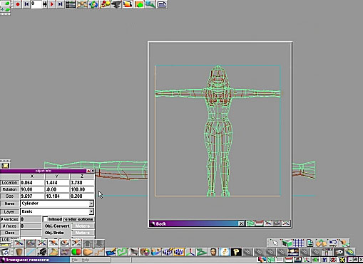
In this instance, rather than use the tools to
do this in the 3D windows, I am going to type the desired values
directly into the Object Info box, to set the rotation to
x -90, y 0, & z 0. You can see the UV mapping represented
by the box surrounding the object as seen below, and this aligns
the UV flat to the faces from the rear, which is what we want.
Here is an interesting point to note - the
lighter colors of the Bounding Box for the UV mapping show which
sides are the bottom and left, while the darker (blue colored)
sides are the top and right. This is a good way to know how your
image will map onto the faces from your current view.
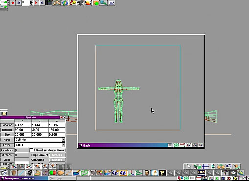
Now resize the UV mapping until it is roughly
twice the size of the model, and then move the UV mapping until
the object appears to be in the the bottom corner left corner.
This is easily done by using the Size and Move
tools just as you would for any other object, or by using the
active Bounding Box around the UV mapping. Alternatively,
you could type the values for Size and Location
into the Object Info box if you wish.
The end result that I am looking for can be seen
below:
| Opening The UV
Editor For The First Time |
Now open
the UV Editor by clicking on its icon. You will see the
UV mapping only for the selected faces, and they fit into the
image that will later act as our texture map as seen in the UV
Editor - if we were to export now, and paint over the area of
the image with the wireframe shown, we would in effect be
painting onto the selected faces of our model.
While the faces are selected, you can move and
scale the faces to place them where you like on the texture map.
Remember that the larger you make it, the more detail you will
be able to paint onto that selection, but also remember we have
a lot of other parts of the model that we have not yet
positioned on the texture map!
Here is one point you might like to note - when
you open the UV Editor, you see the entire texture. It is then
possible to zoom or move your view within the UV Editor, for
instance using the widget in the bottom right hand corner. If
you want to reset to the default view, where the UV Editor shows
the entire texture and no more, and correctly aligned in the UV
Editor window, simply close and re-open the UV Editor window.
Please note that if you had the window displaying information
for a selection of faces, as we have here, you would need to
reselect those faces again before opening the UV Editor window,
as otherwise it will show ALL parts of the model in the window,
and we have not yet positioned the other parts of our model!
In the image below, you can see that I have
scaled up the faces for the back of our figure, so that I can
paint on them in more detail.
| Mapping The Front Of
The Model |
Now we need to repeat this procedure for the
front of the model. Select a front view, then use the Point
Edit:Faces and Select Using Rectangle tools to select
the front faces, and again apply a Planar UV Mapping.
This time use a rotation of 90, 0, -180 for the UV Mapping. You
will also want to Scale and Move the UV Mapping so that the
object appears in the bottom right of the UV Map plane, which
will place it in a different section of your final texture.
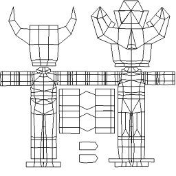
I have positioned things so that the left image
is the character as viewed from the back, and the right image is
the character viewed from the front. Please note that these are
"mirrored" in that the back view has the character's left hand
shown on the left (just as if you were viewing the character
from behind), and the front view has the character's left hand
shown on the right (just as if you were viewing the character
from in front). You can arrange things differently by adjusting
the rotation of the UV Mapping when you apply the Planar UV
Mapping option, it is up to you.
| Mapping The Rest Of
The Faces |
There are some areas that are not going to work
just by UV mapping the front and back of the model - what about
the underside of the character's feet?! Since they face straight
down, they have not been accounted for just by using the two
planar front and back maps, and remember our initial rule which
says every polygon must be accounted for.
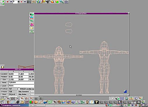
As an example, I will do the bottom of the
character's feet. Select both those faces (you can use the
Select Using Rectangle though this might grab other faces
too - with a small number of faces it might be easiest just to
select the faces one by one, using CTRL + click to add them to
the currently selected faces). Then open the UV Editor and move
the polygons for the feet to wherever you like, and probably
scale them down unless you intend to add a lot of detail to the
soles of the character's shoes!
You can see the polygons for the bottoms of the
feet in the example below:
This is an important
point, that you don't have to apply a UV projection to groups of
faces, you can apply a UV map for just one face if its at an odd
angle, or even for polygons that aren't connected or don't touch
(like the ones on the soles of the shoes here).
By the way, if you are
having a hard time locating a face in the UV mapping, close the
editor and then on the model select the face that you cant find,
then open the editor again. Only that one selected face will
appear. You can then decide how you wish to deal with it to make
it easier to find!
Some parts of a model are more important than others, and as
such will require more detail on the texture map. Usually this
is areas such as the head or face, which people tend to pay a
lot of attention to. Remember, extra detail means using a larger
amount of the texture map for those parts.
In our example, we applied
UV mapping to the head in the back and then in the front when we
applied the planar UV mapping to our selected faces. We could
have selected those faces separately and applied UV mapping
specifically to those back then; or we could select them now and
apply UV mapping to them separately. However, another
alternative is to do all this work inside the UV Editor itself.
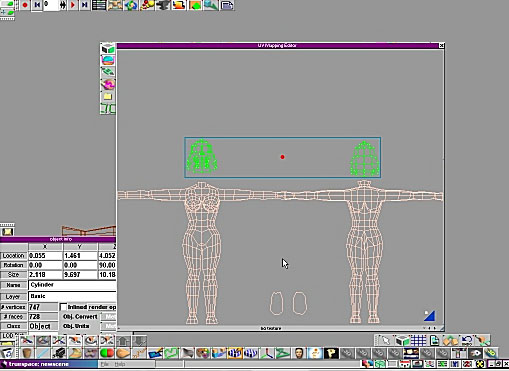
In the UV Editor, use the
Select using Rectangle tool to select the faces you want
to add more detail for. In this case, I have selected the
polygons that make up the head, and in fact I have selected the
polygons for the head from the back view and the polygons for
the head for the front view at the same time.
If I were to move these at
this point, the polygons would stay connected to the polygons
making up the neck (try it and see - you can use CTRL Z to
undo). We don't want that! We want to make the head polygons
entirely independent of the other polygons in the model.
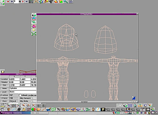
A simple click on the
Break Mesh Along Edges tool is all it takes. Then the selected
polygons detach themselves from the others, and can be
manipulated separately - below you can see the polygons for the
front and back of the head being "lifted off" of the body
polygons. I can then select the front and back polygons
independently, and resize each group as I want.
First, you will notice how I have done a little work
re-arranging the layout of the mapping, increasing the size
given to the head so I can add more detail there.
This means I am now ready to save my set up from the UV
Editor so that I can start painting a 2D texture to apply to my
model. To do so, use the Export Bitmap option to save the
map as an image in .BMP format.
You can easily save straight to the blank image you applied
to the model earlier, or to another location if you choose. What
you get is an image that contains the wireframe layout of your
mesh, just as you arranged it in the UV Editor. This means you
can now begin painting details onto the wireframe representing
the head, the hands, the body, etc.
One handy tip here is to use layers, if your 2D application
supports them. If you place your wireframe on one layer, you can
paint over it on another layer without destroying the original
wireframe beneath. This lets you see exactly what part of your
model you are effectively painting onto, and allows you to
change and repaint without wondering just where that original
wireframe guide was, as you will still have it untouched beneath
the layer you are using to paint your texture!
Be sure you save your model as soon as you
close the UV Editor, so that you don't forget and lose
all your hard work! The UV mapping saves right along with your
model in either the Object or Scene libraries, so save now!
The above example may not be as far as we want
or need to go. It is possible to refine the texture further by
separating different body parts and arranging them on the UV
projection to make the most efficient use of the space on the
texture. For example, the hands may require their own UV
mapping, or you could even map each leg separately (for example,
applying a cylindrical UV projection to the legs and arms, and
perhaps a cylindrical one to the torso even).
Whichever way you choose to work, make sure you
know where each faces join together, and which face is which
body part (you don't want to forget that those odd looking
almost-oval shapes are the soles of his shoes!).
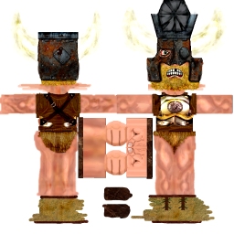
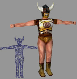
Below you can see a finished example. Top left is the
unwrapped image saved from the UV Editor. This acted as a
template for painting a texture map to add on the details to our
model, and you can see how I have given more space to the head
than the body, and I have separated out the hands here too and
made them quite large to give them a lot of detail.
On the top right you can see the texture I painted for this
particular character. You can see how important it is to
remember which polygons represent what - it is not obvious in
the first template that the polygons in the center are for the
hands, though you can see that in the texture map I have
painted.
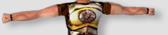
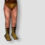
Finally, at the bottom is a grab from inside gameSpace
showing how it looks when we apply our texture map onto our game
model.
This character from start to finish took about 7 hours from
idea to game readiness. Thanks to the template, this character
has 6 different textures (not shown here) that make him look
totally different! It's easy to do that now that the UV mapping
is set up and I have my wireframe guide to paint onto. Bear in
mind you can go for more realism or for a more cartoon look or
any other style that you choose - creating the 2D texture map is
a skill in itself!
|